Index/
Cooling Tower Calculator/
Mechanical Forced Draft Cooling Tower
Drawing No. EH–TH–029 // Thermal Engineering & HVAC
Mechanical Forced Draft Cooling Tower
Reviewed August 2026
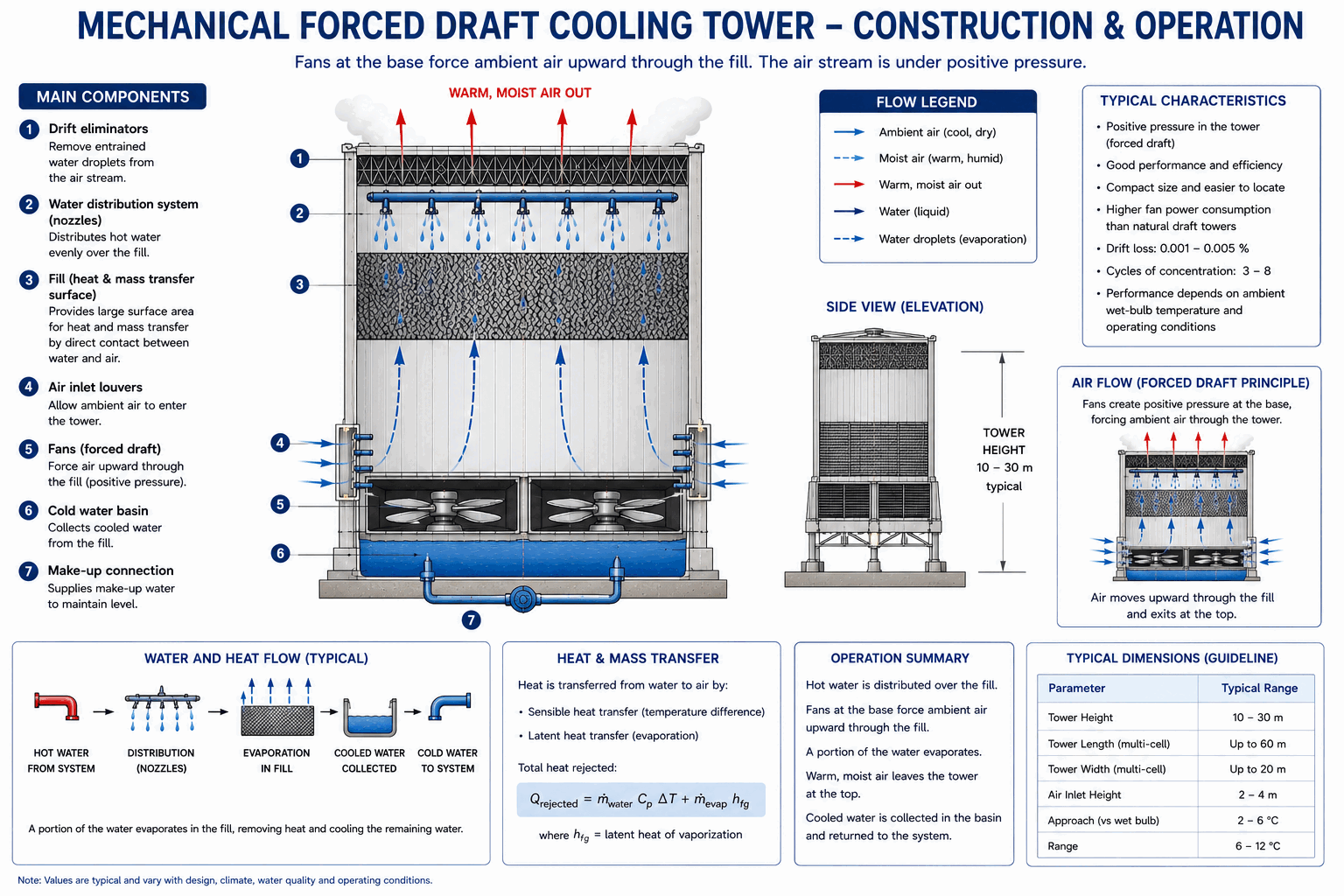
A fan at the base pushes ambient air horizontally through the fill while water falls vertically — keeping the fan and motor out of the humid exhaust air stream, at some cost in thermal performance.
CrossflowFan at baseEasier maintenance
How It Works
A forced draft tower places its fan (or fans) at or near the base of the structure, pushing ambient air horizontally into and through the fill under positive pressure, rather than pulling it up from above. Water, meanwhile, is distributed from basins at the top of the fill and falls straight down under gravity. Air and water paths therefore cross — air moving horizontally, water moving vertically — which is why this is the classic crossflow configuration, distinct from the counterflow arrangement typical of induced draft towers.
In a crossflow fill, the air entering at the front of the fill contacts water across its full temperature range — from hottest at the top to coldest at the bottom — all along a single horizontal pass, rather than tracking the water's temperature change the way counterflow air does. That gives crossflow a less favourable average driving force than true counterflow for the same fill volume and flow rates, which shows up directly as needing somewhat more fill height or air flow to hit the same approach a counterflow tower would reach with less.
The defining practical advantage is where the fan and motor sit: in ambient inlet air, not in the warm, saturated exhaust. That is a meaningfully easier environment for rotating machinery — cooler, drier, less corrosive — and it puts the fan and motor at or near grade level rather than on a deck above the fill, which is a genuine, everyday maintenance advantage: technicians can service the equipment without working at height inside a humid exhaust stream.
Water distribution in a forced draft, crossflow tower is typically gravity-fed from open basins with metering orifices at the top of the fill, rather than the pressurised spray systems some counterflow towers use. That is mechanically simpler and less prone to nozzle clogging, though it does mean the water distribution system occupies useful cross-sectional area at the very top of the structure.